Category: Tips

Color Images using only Red and Green filters

Color Images using only Red and Green filters

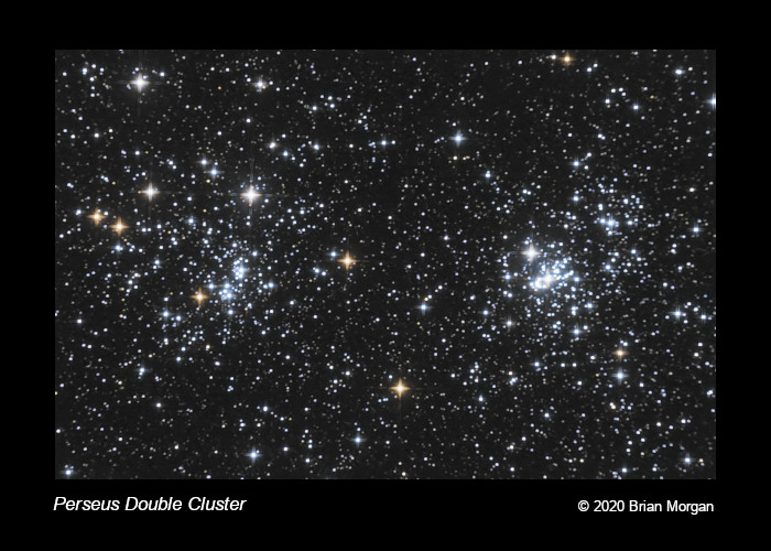
In my last post, I described how to capture tack-sharp images with my refractor by filtering out blue light using a Wratten #12 filter. The question remained: How can I capture color without blue?

The first thing to realize is that stars emit a continuum of colors from red to blue wavelengths. A red star strongly emits red light, but somewhat less blue. Likewise, a blue star strongly emits blue light, but somewhat less red. Green is sandwiched between red and blue. A red star is strong in red, less strong in green, and even less in blue. A blue star is strong in blue, less strong in green, and even less in red. We can take advantage of the difference between red and green to produce blue.

I borrowed a technique used in narrowband imaging. Narrowband filters are used for emission nebulae. Emission nebulae do not emit a continuum of colors. They emit discrete wavelengths. Most emission nebulae contain large amounts of hydrogen, varying amounts of oxygen, and some sulfur. The atoms are excited by the photons from nearby stars. Hydrogen emits several wavelengths but the prominent one is Hydrogen Alpha, abbreviated “Ha”. Ha emits light at the discrete wavelength of 6563 Angstroms. Doubly-ionized Oxygen, OIII, emits at 5007 Angstroms, and singly-ionized Sulfur, SII, emits at 6724 Angstroms. To the eye, SII is deep red, Ha is middle red, and OIII is bluish-green.

In narrowband image processing, it is common to assign SII to red, Ha to green, and OIII to blue. This is known as the SHO palette, made famous by the Hubble Space Telescope. SHO is also known as the Hubble Palette, but there are many other combinations that we can use. There is one called the HOO palette for cases where you only have Ha and OIII data. Exactly one year ago, I imaged the Tadpole Nebula in Ha and OIII. I used the HOO palette.

The HOO palette means that you assign Ha to red, and then split OIII, 50% to green, and 50% to blue. For my tastes, I am not fond of assigning 100% of Ha to red. It comes out screaming red which hurts my eyes. To soften it, I borrowed a technique from Sara Wager who splits Ha between red and green, and OIII between green and blue. The result is a pleasing reddish-orange for hydrogen and cyan for oxygen.

Now, getting back to the topic of this post. I only have data for the red and green filters, but I need to distribute it among red, green, and blue in order to make a color image. It sounds a lot like the HOO palette, doesn’t it? The solution is to split red filter data between the red and green channels, and to split the green filter data between the green and blue channels. It works remarkably well, although red stars appears slightly orange, and blue stars appear slightly cyan. All in all, I like the results. It gives me a way to breathe life into my refractor.

Technical details:

Perseus Double Cluster: NGC 869 and NGC 884

William Optics ZenithStar 71 Achromat
Atik 314E Mono CCD
GSO Wratten #12 filter as Luminance
Optolong Red and Green filters
The Flatinator with Newtonian Mask

W12: 26x60s
R: 70x60s
G: 35x60s

Color Combine:
W12 => L
67% R => R
33% R + 33% G => G
67% G => B
Luminance filter vs Wratten #12

Luminance filter vs Wratten #12

Don’t be misled by deceptive marketing that promotes a refractor as “APO-like.” I fell for it because I am always looking for a good deal. Well, this deal didn’t pay off. In essence, I purchased an Achromat with ED glass. Frankly, I don’t know how much of an improvement the glass makes, but I recommend paying the price for an actual APO.

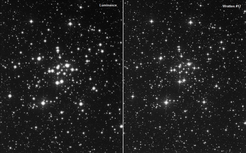
I have known for quite some time that my refractor cannot focus blue. Red is excellent, green is OK, but blue is a mess. Over two consecutive nights, I imaged M34. The left-hand image uses my standard Optolong luminance filter. The right-hand image uses a Wratten #12 (minus blue.) The comparison is stunning. Now all I need to do is figure out how to capture color!

Newtonian Mask

Newtonian Mask

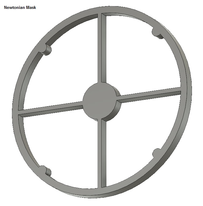
I’ve only owned refractors. In my opinion, refractors are great for lunar and planetary imaging, but I have also seen outstanding images taken by fast refractors. Lately, I have become smitten by reflectors, although I do not own one. One thing I like is the diffraction pattern produced by the secondary mirror assembly. I wanted to see if I could simulate it using my refractor. I watched YouTube videos where people used dental floss stretched across the dew shield, but I wasn’t too happy with the results. So, I decided to create my own using a 3D printer.

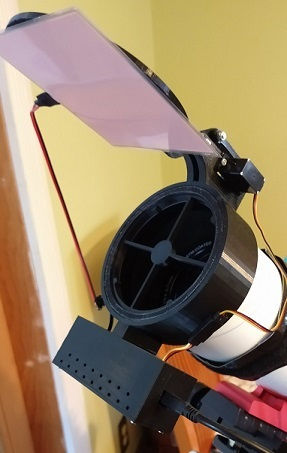
The first attachment shows a 3D model of the profile of a secondary mirror and vanes, plus some imitation screws that add spice to the diffraction pattern. I created it using AutoDesk’s Fusion 360. The next attachment shows the mask inside my flat-field device, something I call “The Flatinator.” I built it two years ago from a concept I had. In the image, you can see the mask. It is held in there firmly by the surrounding structure, but there is still enough margin that I can rotate it to achieve any desired rotation angle.

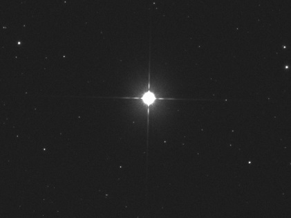
I tested it two nights ago on the star, Almach, in Andromeda. It looks pretty spicy! Now I need to try it on a real target.

How to braid with four strands of wire

How to braid with four strands of wire

I am now onto my third stepper motor in two years. The motor is part of my self-designed right ascension drive system with periodic error correction.

When I designed the system I chose a specific stepper motor from an overseas manufacturer. I knew that one day the motor might need to be replaced so I purchased a half dozen. That first motor lasted more than a year but the second one for only a couple months. Such is the state of quality control. I am now onto my third one.

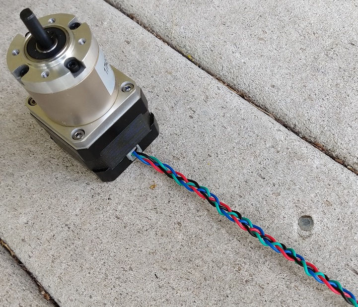
There are four wires coming out of the motor that can easily form a rat’s nest. You need to tame it or else sayounara. For the first motor I used “heat shrink tubing” seen here:

https://en.wikipedia.org/wiki/Heat-shrink_tubing

but I needed to chain quite a lot of them together to meet the requisite length of 20 inches. Furthermore I needed a “heat gun” in order to shrink the tubing. (If you are adventurous you can use a butane lighter.)

For the second motor I did not have enough tubing so I looked online for other solutions. I came across this 3-minute YouTube video on how to braid four strands (of anything):

It works for me although I should mention that you should ask your significant other to help straighten the wire before attempting to braid it. The stepper motor manufacturer did a poor job of preparing the wire for shipment. It looks like someone twirled it around their fingers a few times and then stuffed it in the box.

I’ve attached a photo of the braided wire after I got done. (Remember “Turn” and “Cross”, “Turn” and “Cross”…)

What a difference two years makes

What a difference two years makes

I am writing to affirm that progress is inevitable but only with heaps of patience and experimentation.

Two years ago I had the same telescope as today. So what’s the difference? The camera, but not what you think. It was how I was using it.

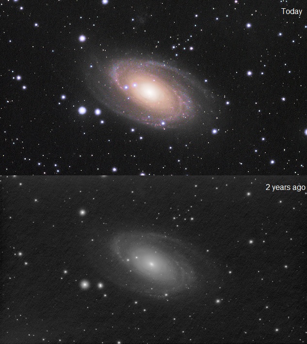
The top image, the one in color, was taken with the Atik 314E CCD, and the bottom image with the Altair 290M CMOS camera.

Don’t get me wrong. I’m not making a pitch for CCD over CMOS. I am saying that the exposure you choose makes all the difference in the world.

The bottom image used the subframe exposure of 4.7 seconds. Total integration time was 60 minutes. It may not be clear in this small image but it suffered from a severe case of “raining noise”. This was a common ailment of my early images. Without going into a lengthy explanation the cure was to increase the exposure.

The question is always “How far do I increase the exposure?” You can always experiment. A good test is to keep the total integration time the same, in my case 60 minutes, but you can choose 30 minutes if you want to test a greater range of exposures in one evening.

For the Altair 290M and my Bortle 5 skies it turns out that 30 seconds is optimal. You can increase it farther but image quality, signal-to-noise (SNR), won’t improve that much. You can decrease the exposure but then you will see a dramatic drop-off in SNR. If you decrease exposure too far then “raining noise” will rear its ugly head.

Of course the “optimal” exposure is completely dependent on your skies, your telescope, and camera.

The top image was taken with the Atik 314E using a 90-second exposure over 11.6 hours and LRGB filters. The signal-to-noise ratio is high due to the long integration time so comparing it to the bottom image is not entirely fair. The important point is that “raining noise” was never a problem. I chose a 90-second exposure because a CCD has higher Read Noise than a CMOS camera. I could have gone down to 60 seconds but below that the image would have suffered.

High Dynamic Range (HDR) Photography using Photomatix

High Dynamic Range (HDR) Photography using Photomatix

First Snow 2019
First Snow 2019

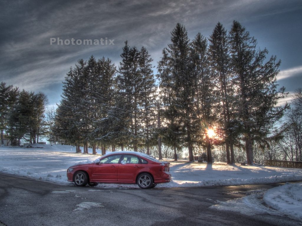
While I wait for the weather to improve for astrophotography I discovered High Dynamic Range (HDR) photography through a friend in Great Britain. HDR is commonly used by real estate agents to capture beautiful sun-drenched living spaces. Astrophotographers have used HDR to capture stunning images of the Crescent Moon bathed in Earthshine and images of Total Solar Eclipses. There might be other applications that I want to explore.

Many years ago I was heavily engaged in conventional photography of landscapes and portraiture. This was at a time before digital photography. Portraits were the easiest to capture since they were obtained in a controlled environment of a studio. Shadows that would normally render in black could be filled with flash or flood lights. Highlights that would normally appear washed out on film could be softened with light diffusers.

By far the most difficult was landscape photography. There you didn’t have the option of using flash, flood lights, or light diffusers. You relied more heavily on darkroom techniques. Things changed with the advent of digital photography.

Photomatix is a software product from HDRsoft Ltd, a UK company. They have several versions, some that integrate well with Photoshop, others that are standalone applications. I chose the standalone version for Linux since I find myself increasingly turning away from Windows in favor of Linux. The trial version never expires and is full-featured but they do draw the Photomatix watermark on your final image. The cost of a license is reasonable at $49. For this test I am using the trial version. The software is very easy to use plus there are many videos available on YouTube to learn how to use it to its fullest extent.

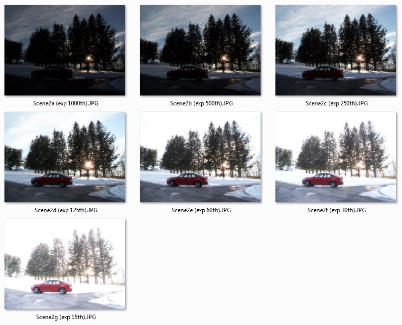
The difficult part is capturing the images. Instead of me yammering on attempting to explain what to do, allow me to present the seven photos that I input into Photomatix:

Exposures from 1/1000s to 1/15s

The essential parts of the scene are the sky, the snow, the car, and the snow on the limbs of the trees. The sky and the snow on the ground are the brightest parts. The car and tree limbs are the darkest. The objective is to capture detail in all of them. Notice that there is no single exposure that satisfies us. Perhaps the closest is “exp 60th” but notice how the sky is completely blown out. This scene is a perfect candidate for HDR using Photomatix.

Notice that my exposures range from 1/1000s to 1/15s. I chose 1/1000s because it showed the best detail in the sky and the snow on the ground. I chose 1/15s because it showed the best detail in the car and the tree limbs. Once I determined those endpoints then I proceeded to capture images in full-stop increments: 1/1000s, 1/500s, 1/250s, 1/125s, 1/60s, 1/30s, 1/15s. It is important to keep the same f/stop. In my case it was f/7.

My camera is rather old so it does not have auto-bracket mode. No worries, I used manual mode instead. My camera has an integrated spot meter. Wherever I point the camera it will read out if it is under-exposed or over-exposed. The meter readout is around the center of the view.

The steps are:

  1. Choose an f/stop.
  2. Adjust the zoom to frame the scene as you like.
  3. Point the camera at the brightest part of the scene, in my case the sky and ground snow.
  4. Adjust the exposure setting so that the meter reads zero (neither under-exposed nor over-exposed). Make a mental note, in my case 1/1000s.
  5. Point the camera at the darkest part of the scene, in my case the car and tree limbs.
  6. Adjust the exposure so that the meter reads zero, in my case 1/15s.
  7. Attach the camera to a tripod.
  8. Double-check the framing.
  9. Click the button to capture the frame. (This should be at our current setting of 1/15s.)
  10. Adjust the exposure one full-stop, in my case 1/30s.
  11. Click the button to capture the frame.
  12. Repeat these steps until you capture the last frame at the terminal exposure, in my case 1/1000s.

That’s it! Download the images to your computer and process in Photomatix. I’ll leave that activity for you to figure out. There are plenty of video resources for that. Good luck!

What makes the PacMan Nebula light up?

What makes the PacMan Nebula light up?

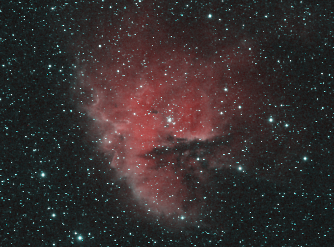
A former co-worker who has an interest in astronomy prompted me to answer the title question: “What makes it light up?”

To understand what is happening look at a neon sign. It is made up of a tube of neon gas atoms. On both ends of the tube a very, very high electric voltage is applied. The electric energy temporarily strips a neon atom of one of its electrons. A fraction of a second later that electron rejoins the atom and when it does a photon of light is emitted. The wavelength of that light is very “narrow”.

Notice how I used the term “narrowband” in the previous post. What this means is that I use a filter that passes only a narrow band of light. Different atoms emit different wavelengths of light. Hydrogen is different from sulfur which is different from oxygen. By using different filters I can tell which elements make up a cloud of gas in outer space.

The last question to answer is where does the “very, very high electric voltage” come from in outer space? The answer is that it doesn’t have to be an electric voltage, just something that is highly energetic. If you look at the center of the PacMan nebula you will see a bright star and several stars around it. That cluster of stars emits a lot of energy which causes the gaseous nebula to light up somewhat like a neon sign!

The PacMan Nebula is known as an “emission nebula” not to be confused with a “reflection nebula”.

My Gear

My Gear

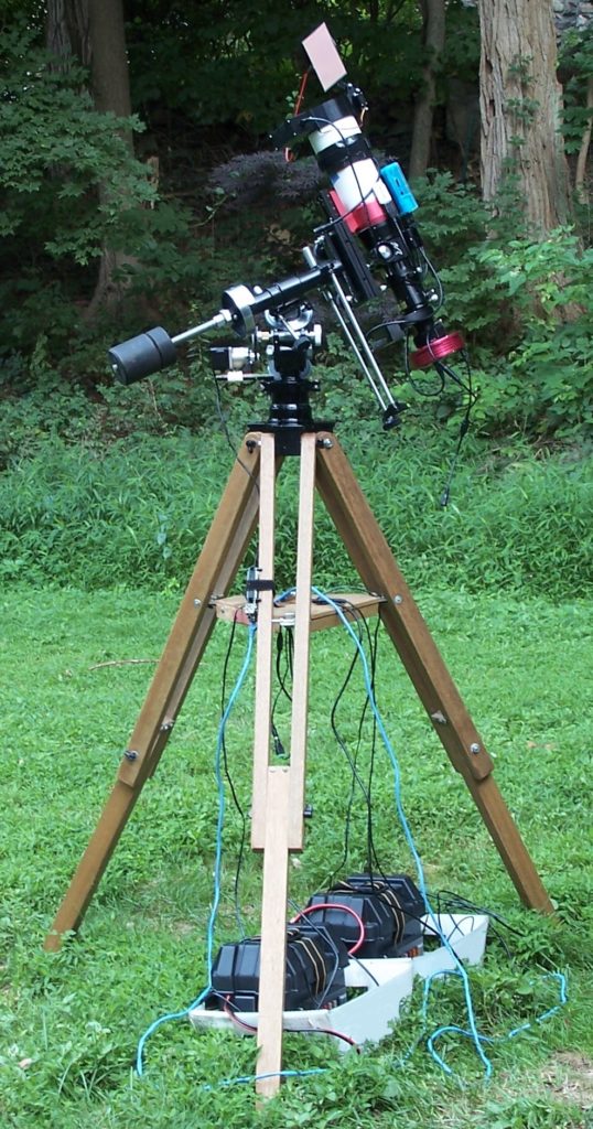
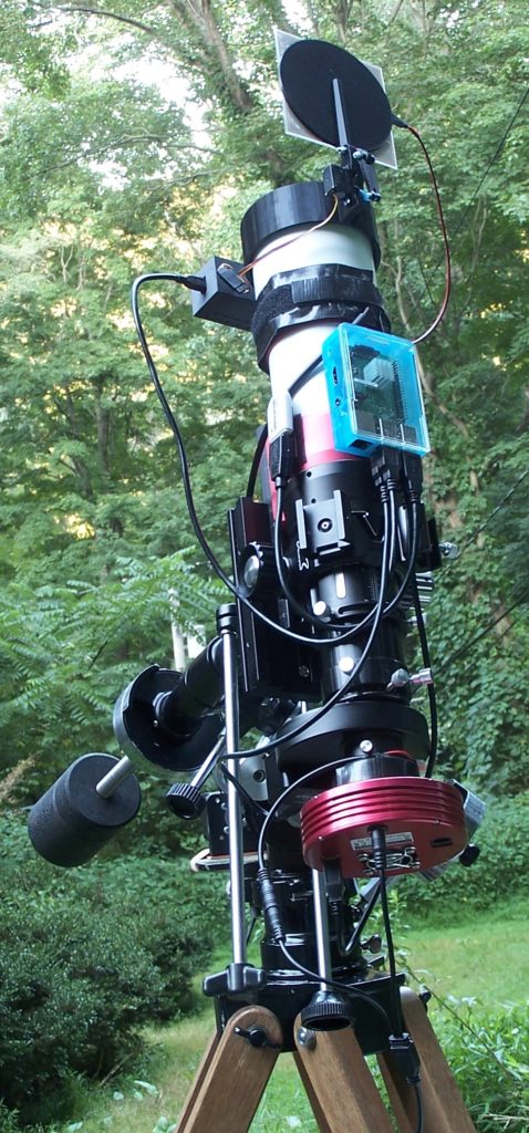
Here are recent photos of my telescope as I was setting up to image the Andromeda Galaxy Mosaic. Noteworthy items include:

  • Astroberry/KStars/Ekos/INDI using RasPi Model 3B+
  • Unitron Model 152 German Equatorial Mount (50 years old and running great)
  • William Optics ZenithStar 71mm f/5.9 (20th Anniversary Edition)
  • Atik 314E CCD (used, approximately 10 years old)
  • ZWO 5-filter Electronic Filter Wheel (EFW), Optolong LRGB filters, and Orion dark filter
  • Altair 290M CMOS camera & 200mm finder/guider scope for polar alignment (not pictured)
  • Flatinator flat-fielder and dust cover (my own invention)
  • Permanent Periodic Error Correction (PPEC) using RasPi Model 3B and Stepper Motor (my own invention)
  • OMC Steppers-Online Motor with 26.85:1 Gearbox
  • Dew heater strips on objective and sensor window (DIY from plans by “DewBuster”)
  • Two Interstate DCM0035 12VDC 35Ah Deep-Cycle Batteries
  • Two West Mountain Radio U1 Battery Boxes with fused distribution panels
  • Various PowerPole connectors and USB cables
  • One DROK 12VDC Buck/Boost Converter for regulating power to the camera
  • Two Adafruit UBEC 12VDC-to-5VDC regulators for powering the RasPi’s
  • One Adafruit Stepper Motor HAT for RasPi
My gear from afar.
Close-up of my gear.
You’ve got a Dew Management problem

You’ve got a Dew Management problem

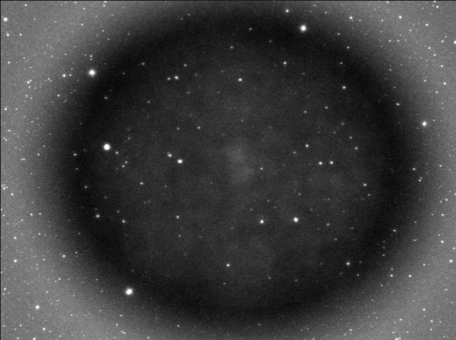
Dew is condensed water vapor that likes to form on optical surfaces whenever the relative humidity is high. The featured image shows a dew drop that formed on my camera’s sensor window shortly after I turned on the thermo-electric cooler. It ruined a night’s worth of astrophotography because I did not have a plan in place.

My first experience with dew was two years ago. The sky was clear but I could see my breath and the grass was glistening with moisture. When I began my imaging run the computer screen showed bright stars and dark space but as the night wore on I noticed that the image looked increasingly less defined. When I shined a light on the objective lens of my refractor I saw that it was fogged over.

Don’t let this happen to you. Clear nights are hard to come by so don’t waste it by not having a dew management plan. There are several vendors who have solutions that consist of heater bands and a controller for adjusting the temperature. Me, I am a Do-It-Yourself person, so I like to build my own. I’ve built a couple homemade heater strips as described here at DewBusters website:

http://www.dewbuster.com/heaters-330ohm-resistors.html

I don’t have a controller so if you build a heater strip according to those specifications you will find that it runs hot when you apply a constant 12VDC across it. Now I tend to build strips with half the number of resistors such that it runs at half power. I solved the dew problem on my sensor window by building a small heater strip that fits nicely around the camera’s nose-piece using Velcro.

The other night as I prepared to image the Eastern Veil Nebula I purposely disconnected the dew heaters earlier in the evening to conserve battery power as I waited for the target to rise above the treeline. When the time came I engaged the cooler, waited 20 minutes for the temperature to stabilize, and then took a test shot. Right away I knew what the problem was. I ran outside, reconnected the dew heaters and after only five minutes I could see the dew had evaporated.

The Debate over Short Exposures

The Debate over Short Exposures

There is a raging debate over short exposures vs long. The decision to use one over the other is multi-faceted. Here are some reasons to consider short exposures over longer ones:

1. Your mount isn’t up to the task.
2. You live in a zone where aircraft frequently buzz by.
3. You have clear skies but with intermittent clouds.
4. You are a EAA practitioner.

If none of these apply to you then you should open yourself up to the benefits of longer exposures. I’d like to present two examples. The first one has both signal and noise so it easily applies to imaging:

1. Imagine it is the dead of night and the world is asleep. You wake up suddenly and whisper to your partner: “Did you lock the front door?” Their reply is “Yes, now go back to sleep.” This conversation was possible due to a low-noise environment. Now consider a high-noise environment like Niagara Falls and try to whisper. Nope, doesn’t work. You need to raise your volume. Some people might interpret this as the reason why you need longer exposures with CCDs. This is true but please understand that CMOS and CCD both benefit from longer exposures. Imagine that you are back at Niagara Falls and your partner finally finds a voice level that you can just make out, barely. Doesn’t it seem reasonable to ask for louder voice levels just to be absolutely, positively clear what they said?

This next example is an analogy. Take it for what it is worth but I think it does a good job of explaining why increasing exposure is beneficial even when it means that you are recording high levels of sky glow:

2. Imagine that you are at an automobile drag strip. One car can travel at a maximum speed of 100 feet per second and the other at 110 fps. Assume that when the light turns green that they can immediately accelerate to their maximum speed. After 1 second they have traveled 100 ft and 110 ft, respectively. Only 10 ft separate the two. After 2 seconds they traveled 200 ft and 220 ft. Now 20 ft separate the two. You can see that the distance separating the two vehicles steadily increases as time goes by. This is the same with imaging. After 1 second you have only 10 units of brightness separating galaxy from sky glow. But after 2 seconds you have 20 units of brightness separating them. And so on.

Like I said not everyone can run longer exposures for the reasons that I listed above but there is one other consideration to be mindful of. Foreground stars are the brightest objects in your field of view. The longer you keep your shutter open the more the risk of saturating the brightest stars. The saturation level is very much dependent on your camera. CCDs are very good at this because they generally have much deeper ‘wells’ than CMOS and can hold more electrons (i.e. photons). But this is all a matter of taste. Personally I don’t like saturated stars so I try to crop them out when I can.

Finally, what about stacking? Stacking helps increase signal-to-noise in both CMOS and CCD, however keep in mind this inequality: 100x 1-second exposures does not equal 1x 100-second exposure. You will always get better results in less total time when increasing exposure. You don’t have to go crazy. Just try doubling and then go from there.

The fallacy of the perfect exposure:

Your choice of exposure is akin to a multi-lane highway — both have boundaries. Highways have shoulders — veering one way sends you into a gully, and the other way into oncoming traffic. Likewise with imaging, too short of an exposure records nothing of interest, and too long saturates stars and potentially damages the frame by passing aircraft and clouds. What lane you travel in depends on your skill level and risk tolerance.